Castor Tutorial
Learn Castor by building a TODO list application. Walk through requirements, diagrams, code generation, and round-trip synchronization.
Introduction & Setup
In this tutorial, you'll learn how to use Castor by working with a TODO list project. You'll start with existing requirements, generate diagrams and code, add new features, and see how Castor keeps everything synchronized.
Prerequisites:
- Storage: 1.41GB free space
- Memory: 4GB minimum (8GB recommended)
- Operating System: macOS 10.15+ or Windows 10/11
- Castor Account: Create an account if you don't have one
- Git: Installed on your machine
Before you begin:
- Download and install Castor
- After installing, open the IDE and log in to your Castor account
Clone the Demo Project
We've prepared a TODO list demo project that has some requirements already defined. You can clone it using one of these methods:
Option 1: Clone from Terminal
git clone https://github.com/JustinSciortino/castor-todo-demo.gitThen open the folder in Castor via File → Open Folder.
Option 2: Clone from within Castor
- Copy the repository URL:
https://github.com/JustinSciortino/castor-todo-demo.git - Open Castor IDE
- Press Ctrl+Shift+P / Cmd+Shift+P to open the Command Palette
- Type Git: Clone and select it
- Paste the repository URL and press Enter
- Choose a folder to clone into and click Select as Repository Destination
- When prompted, click Open to open the cloned project
About the Demo Project:
This is a NestJS TODO list application. It comes with a requirements.md file containing 3 requirements: Create Task, View All Tasks, and Mark Task as Complete. You'll use Castor to generate the design, diagrams, and code from these requirements.
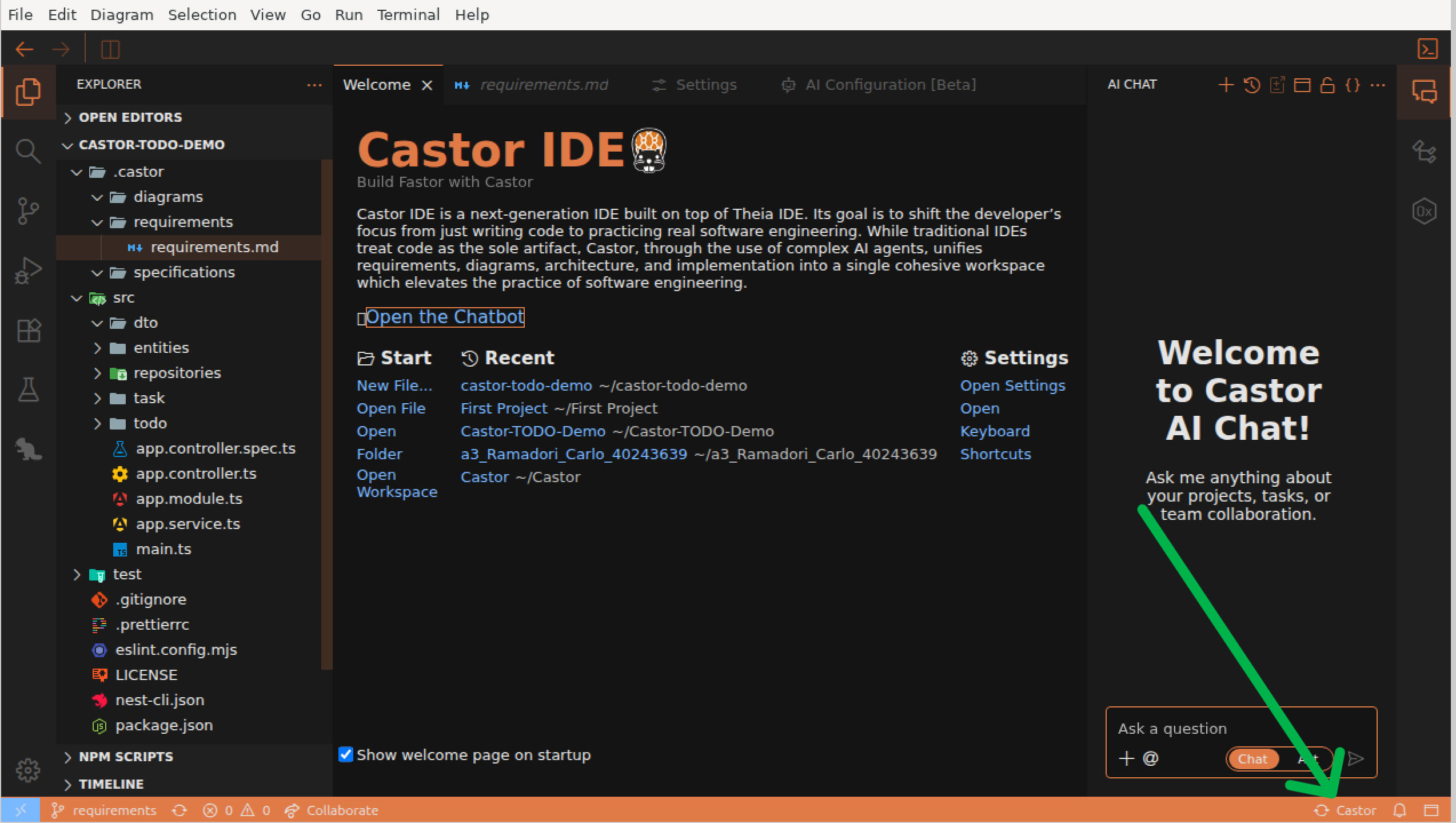
Exploring the Castor Panel
The Castor Panel shows all your project artifacts: requirements, design documents, and diagrams. Let's explore what's in the demo project.
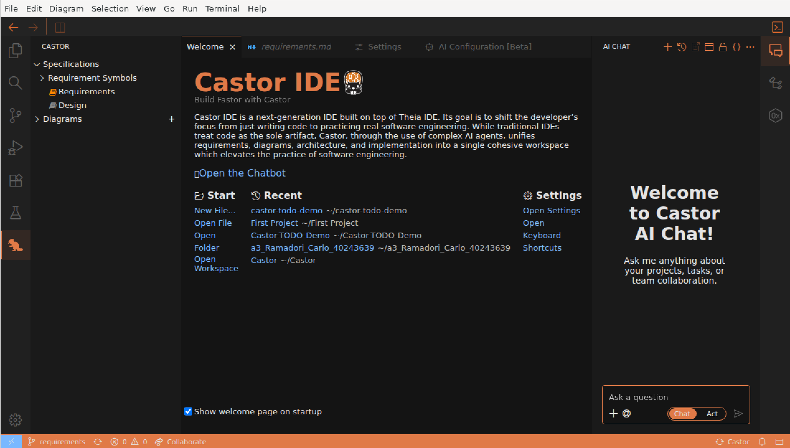
Opening the Castor Panel
- Look at the Activity Bar on the left side of the IDE
- Click the Castor Beaver icon to open the Castor Panel
What You'll See
The Castor Panel displays your project artifacts in a tree structure:
- Requirements: The requirements.md file containing the 3 existing requirements (Create Task, View All Tasks, Mark Task as Complete)
- Design: The design.md file
- Diagrams: All supported diagrams for your project
File Icon Colors:
Notice the icon colors in the Castor Panel: an orange icon indicates the file exists, while a grey icon means the file hasn't been generated yet. Right now, only requirements.md should be orange.
View the Existing Requirements
Click on requirements.md to open it. You'll see the structured requirements:
- Create Task: Users can create tasks with a title and optional description
- View All Tasks: Users can retrieve a list of all tasks
- Mark Task as Complete: Users can update a task's status to complete
Generating Design & Diagrams
Now let's use the DAM agent to generate the design document, diagrams, and code from the existing requirements.
Open the AI Chat
- Click View → AI Chat in the menu bar
- The Chat Panel opens on the right side of the IDE
- Type @DAM or use the @ button to select the DAM agent
Selecting a Language Model
Before using the DAM agent, you can select which language model to use:
- Click the three dots menu (⋮) in the AI Chat panel
- Navigate to Agent Settings > DAM > Language Model
- Select any model marked with a checkmark to use it
Tip:
You can access additional model settings through the three dots menu in the AI Chat panel at any time.
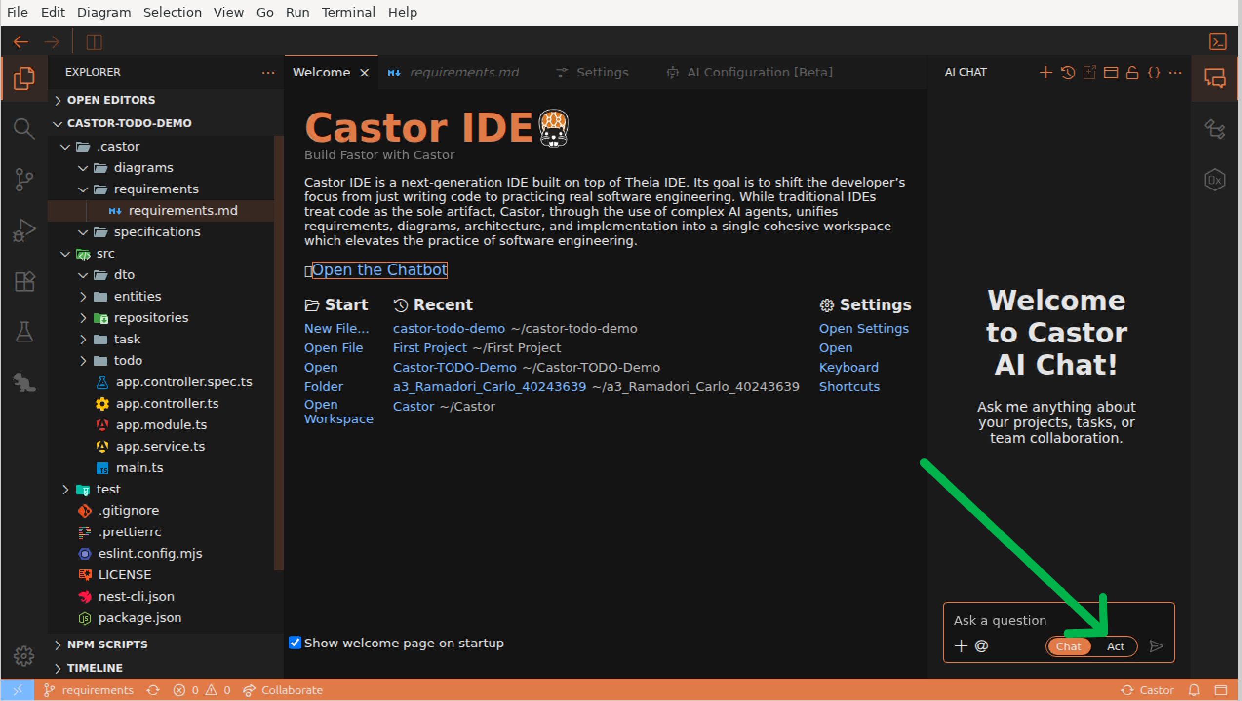
Set the Chat/Act Toggle
Make sure the Act toggle is enabled so the DAM agent will directly create and update your files.
Ask the DAM Agent to Generate
Type a message asking the DAM agent to generate the design and domain model from the existing requirements. For example:
"Generate the design document and domain model based on the existing requirements."
Watch the Generation Process
The DAM agent will:
- Read the existing requirements.md file
- Create a design.md file with architectural decisions and technical specifications
- Generate a domain diagram (.domain.castor) capturing business concepts for requirements traceability
Note: Domain Diagrams vs Code-Generating Diagrams
The DAM agent creates domain diagrams that capture business concepts from requirements. These diagrams are for traceability only and do NOT generate code directly. To generate code, you'll create ERD or Class diagrams (covered in later sections).
Important: Sync Your Changes
Once the DAM agent finishes, click the Sync button in the bottom right of the IDE to synchronize the generated files. This ensures all changes are properly applied.
After Generation:
Check the Castor Panel again. The design.md file should now have an orange icon, indicating it has been created.
Understanding Diagram Types
Castor supports three types of diagrams, each serving a different purpose. Understanding these types is key to using Castor effectively.
The Three Diagram Types
1. Domain Diagrams (.domain.castor)
- Created by the DAM agent from requirements
- Capture business concepts and domain models
- Do NOT generate code - they're for requirements traceability only
- Help maintain alignment between requirements and design
2. ERD Diagrams (.erd.castor)
- Entity-Relationship diagrams for data modeling
- Generate entity files (*.entity.ts)
- Define your data structures, properties, and relationships
- Sync bidirectionally with entity code files
3. Class Diagrams (.class.castor)
- Application architecture diagrams
- Generate services, controllers, and modules
- Produces *.service.ts, *.controller.ts, *.module.ts files
- Sync bidirectionally with application code files
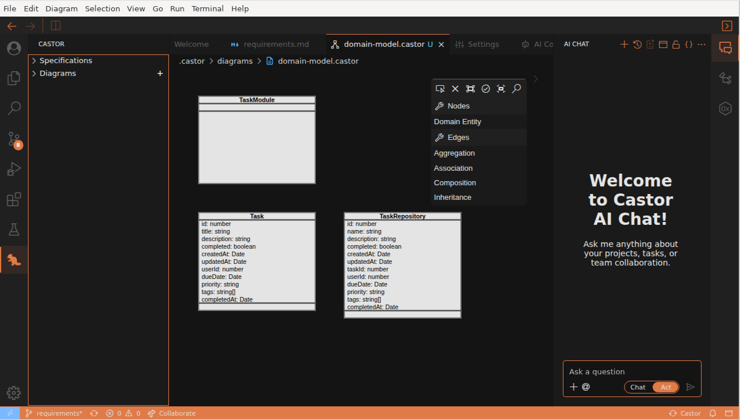
Opening the Domain Diagram
- In the Castor Panel, expand the Diagrams section
- Click on the .domain.castor file to open it
- The Diagram Editor opens with your domain concepts visualized
Understanding the Domain Diagram
The domain diagram shows the business concepts of the TODO application based on the 3 requirements:
- Task: The core domain concept with properties like title, description, and completion status
- Relationships: Lines connecting concepts show how they relate in the domain
Diagram Editor Interface
Take note of the editor components:
- Canvas: The main area where your diagram is displayed
- Palette (right side): Contains elements you can drag onto the canvas
Key Takeaway:
Domain diagrams capture the "what" (business requirements), while ERD and Class diagrams define the "how" (technical implementation). Only ERD and Class diagrams trigger code generation - domain diagrams are purely for traceability.
Creating Code-Generating Diagrams
Now that you have a domain model, let's create ERD and Class diagrams that will actually generate code. Remember: domain diagrams are for traceability only, while ERD and Class diagrams generate code.
Creating an ERD Diagram
ERD diagrams define your data entities and generate *.entity.ts files.
- Right-click in the Explorer or use File → New File
- Name the file with the .erd.castor extension (e.g., task.erd.castor)
- The Diagram Editor opens - drag entity elements from the Palette
- Add properties to your entities (id, title, description, isComplete, etc.)
- Save with Ctrl+S / Cmd+S
Creating a Class Diagram
Class diagrams define your application architecture and generate services, controllers, and modules.
- Create a new file with the .class.castor extension (e.g., task.class.castor)
- Drag service, controller, and module elements from the Palette
- Add methods to your services (createTask, findAll, markComplete, etc.)
- Create relationships between classes
- Save the diagram
Sync to Generate Code
After saving your ERD or Class diagram, click the Sync button in the bottom right of the IDE. Castor will generate the corresponding TypeScript files.
What Gets Generated
From ERD Diagrams:
- task.entity.ts
- TypeORM decorators
- Property definitions
- Relationship mappings
From Class Diagrams:
- task.service.ts
- task.controller.ts
- task.module.ts
- NestJS decorators
File Naming Convention:
Castor uses file suffixes to determine diagram type and behavior:
- .domain.castor → Domain concepts (no code generation)
- .erd.castor → Entity files (*.entity.ts)
- .class.castor → Services, Controllers, Modules
Viewing the Generated Code
After syncing your ERD and Class diagrams, Castor generates TypeScript code. Let's explore the code files.
Finding the Generated Code
- Click the Explorer icon in the Activity Bar (file icon at the top left)
- Expand the src folder
- You'll see TypeScript files corresponding to your diagram elements
Explore the Code Files
Click on different files to see how the diagrams translate to code:
- task.entity.ts: Generated from ERD diagram - the Task class with all properties
- task.service.ts: Generated from Class diagram - service with business logic methods
- task.controller.ts: Generated from Class diagram - REST endpoints with NestJS decorators
Key Observation:
Notice how the code structure matches the diagrams exactly. Classes, properties, and methods in the ERD/Class diagrams correspond to the same elements in the TypeScript files. This is bidirectional synchronization in action!
Adding New Requirements
Now let's add two new requirements to the project using the DAM agent. You'll see how the domain diagram gets updated with new concepts.
Add the New Requirements
In the AI Chat (with @DAM selected and Act mode enabled), copy and paste the following two requirements:
Requirement 4: Delete Task
Users shall be able to permanently remove a task from the system using its unique identifier. The system shall confirm successful deletion or return an appropriate error if the task does not exist.
Requirement 5: Filter Tasks by Status
Users shall be able to filter and retrieve tasks based on their completion status (complete or incomplete). The filtered list shall maintain the same response structure as the full task list.
Ask the DAM agent to add these requirements. For example: "Add these two new requirements to the project."
What Happens Next
After sending the requirements, the DAM agent will:
- Update the requirements.md file with the new requirements
- Update the design.md file with technical specifications
- Modify the domain diagram (.domain.castor) to include new concepts
Remember: Domain Diagrams Don't Generate Code
The DAM agent updates domain diagrams for requirements traceability. To generate code for the new features, you'll need to update your ERD and Class diagrams manually (covered in the next section).
Important: Sync Your Changes
Once the DAM agent finishes, click the Sync button in the bottom right of the IDE to synchronize the changes.
Updating Diagrams for New Features
After the DAM agent processes your new requirements, let's see how the domain diagram has changed and update the ERD/Class diagrams to generate code for the new features.
Check the Updated Domain Diagram
- Open the Castor Panel and click on your .domain.castor file
- Notice the new concepts that were added for Delete Task and Filter Tasks features
- The domain diagram now captures all 5 requirements for traceability
Update ERD/Class Diagrams for Code Generation
To generate code for the new features, update your ERD and Class diagrams:
- Open your .class.castor file
- Add deleteTask() method to TaskService
- Add filterByStatus() method to TaskService
- Add corresponding endpoints to TaskController
- Save and sync to generate the updated code
The Workflow:
Requirements → Domain Diagram (traceability) → ERD/Class Diagrams (implementation) → Code
Domain diagrams help you understand and trace requirements without generating code. ERD and Class diagrams define the actual implementation.
Editing Diagrams Manually
You can make changes directly in the Diagram Editor. Here are the different edits you can make.
Diagram Edits You Can Make
- Add Elements: Drag classes, entities, or services from the Palette
- Create Connections: Use the Connection Tool to draw relationships
- Add Methods/Properties: Select an element and add in the Properties Panel
- Delete Elements: Enable the deletion tool in the Palette and click on elements
Watch this walkthrough to see how to add entities, move them, create relations, and edit attributes and methods:
Remember: Only ERD and Class Diagrams Generate Code
Changes to .erd.castor files generate/update entity files. Changes to .class.castor files generate/update services, controllers, and modules. Changes to .domain.castor files do NOT generate code.
Remember to Save and Sync!
After making diagram changes, save with Ctrl+S / Cmd+S, then click the Sync button in the bottom right of the IDE to synchronize your changes.
Synchronization in Action
Now let's see the magic of round-trip engineering. When you make changes to ERD or Class diagrams and save, Castor automatically synchronizes between diagrams and code.
Check the Status Bar
Look at the bottom right of the IDE:
- When you save, you'll briefly see "Syncing..."
- Once complete, it shows "Synced" with success/failure counts
Try It: Code to Diagram
Synchronization works both ways for ERD and Class diagrams! Try editing the code:
- Open task.entity.ts
- Add a new property: dueDate: Date
- Save the file with Ctrl+S / Cmd+S
- Open the .erd.castor diagram and see the new property appear in the Task entity!
Round-Trip Engineering:
Bidirectional synchronization works between ERD/Class diagrams and code. Whether you prefer working in diagrams or code, Castor ensures both stay in sync. Domain diagrams remain separate for requirements traceability.
Sync Loop Prevention:
Castor automatically prevents infinite sync loops. When sync writes a file, the file watcher ignores that change to avoid triggering another sync cycle.
Congratulations!
You've completed the Castor tutorial! You now know how to use all the core features of Castor IDE.
What You Learned
- How to open and explore projects in the Castor Panel
- Using the DAM agent to generate design documents and domain diagrams from requirements
- Understanding the three diagram types: Domain (.domain.castor), ERD (.erd.castor), and Class (.class.castor)
- Creating ERD and Class diagrams to generate code
- Viewing and understanding diagrams in the Diagram Editor
- Exploring generated code and understanding how it maps to ERD/Class diagrams
- Adding new requirements and updating domain diagrams for traceability
- Manually editing diagrams and adding elements
- How bidirectional synchronization keeps ERD/Class diagrams and code in sync
Next Steps
Now that you understand the basics, try these next:
- Start a new project from scratch and create requirements with the DAM agent
- Create separate ERD and Class diagrams for different features
- Experiment with different diagram relationships (inheritance, composition, aggregation)
- Use domain diagrams to maintain traceability between requirements and implementation
- Explore the full documentation for advanced features
Quick Reference - Diagram Types:
- .domain.castor - Domain concepts (no code generation, requirements traceability)
- .erd.castor - Entity diagrams → *.entity.ts files
- .class.castor - Class diagrams → *.service.ts, *.controller.ts, *.module.ts
Need Help?
If you have questions or run into issues, contact us and we'll be happy to assist. Happy building with Castor!